Knobs on the side of the box provide a gain control and a level control for zero adjustment.
| Load cell is bolted to heavy aluminum plate from underneath,
using threaded holes that were already there. A shim of aluminum is
used to space it up off the plate a bit. This shim is 0.10 inch thick,
and roughly 1 inch by 1.5 inches. Note that the base of the load cell
has a shelf, which provide a little more clearance. Together, these
place the far end of the load cell about 0.12 inches from the base plate.
|
|
|
|
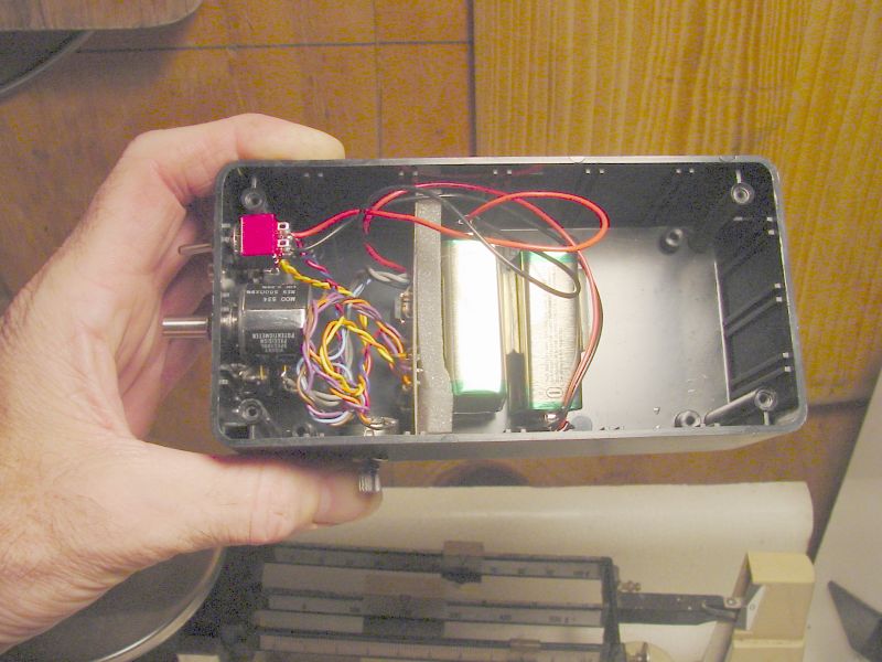
Here
is the interior of the amplifier box. Steve got an extra-large one
with the idea that the innards of the Dataq unit could go in it. I
suspect the Dataq might fit in without removing its own box, just making
a hole for the serial connector at the far end. This would allow the
amp output to be wired to it inside the box, thus one less part to juggle
in the field. Load cell in on one side, serial output on the other.
|
|
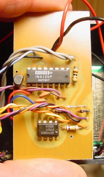
Topside of the amplifier board. It uses the
INA125, but has some other parts. I am an electronics idiot, and so
will not attempt to describe their function. It looks like the basics
in McCreary's book, but with a few extra adjustments, bells, and whistles. Knobs on the side of the box provide a gain control and a level control for zero adjustment. |
|
|
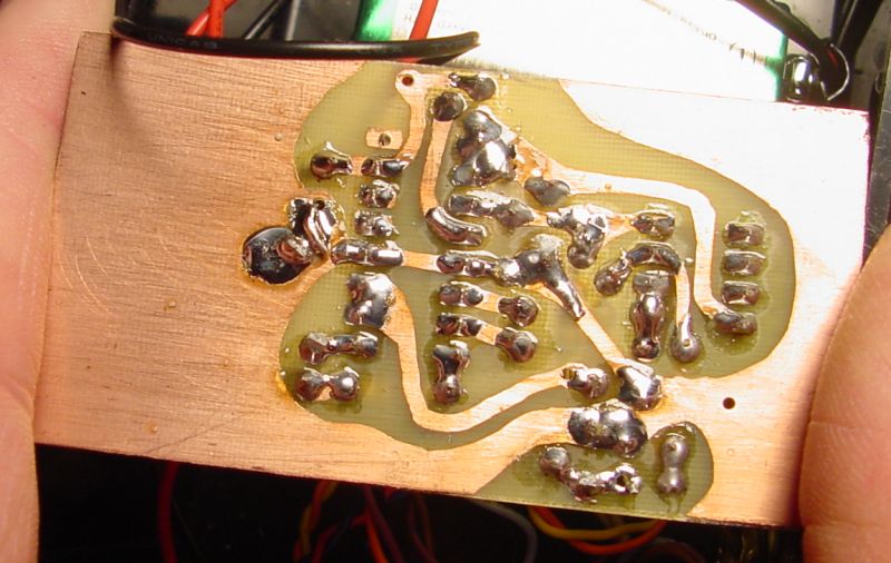
Belly of the hand-crafted circuit board. |