Reloadable Motor Photos
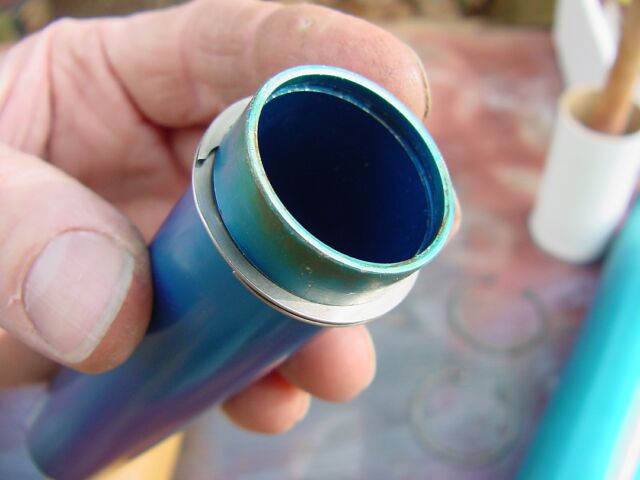
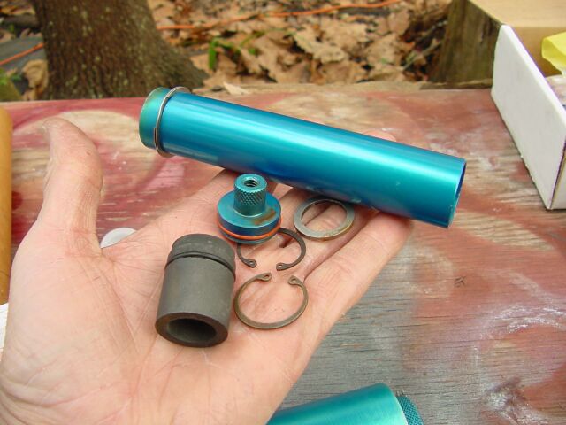
Loki 54 mm 3-grain motor casing


Nozzle is turned from graphite, head-end plug is aluminum. Each has one
O-ring groove, and is held in place by a large snap ring. Some similar
designs use two O-rings on each end which might be a good idea, but I have
had no failures with the single ring design.
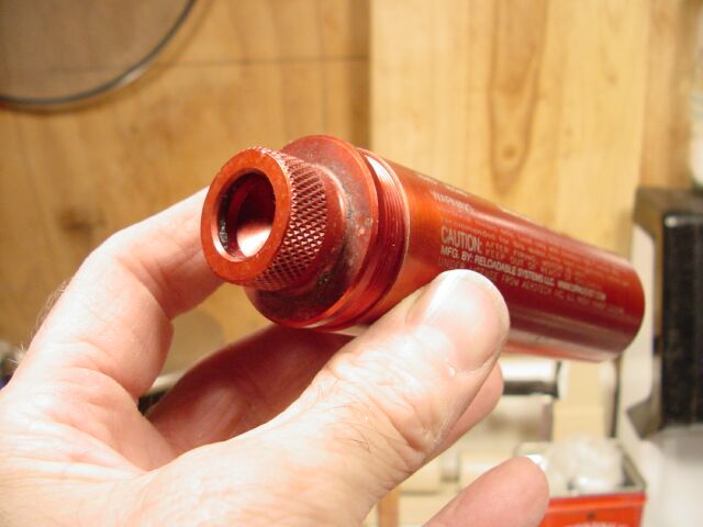
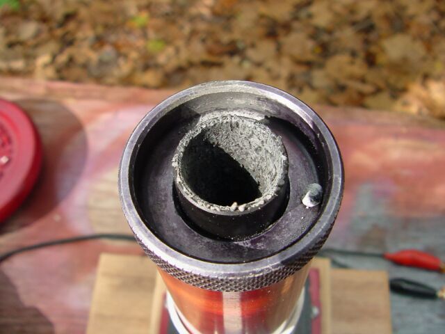
The enlargement at the nozzle end is a "thrust ring" which presses against
the motor-mount tube in the airframe. I understand that Jeff Taylor
had difficulty getting aluminum tubing the right size, so he got some with
the right inside diameter but thicker than needed, and turned off the rest,
leaving this handy ring. Casing thickness is about 0.10 inch, as you can see on my cheesy caipers.
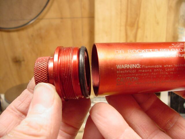
The header plug has a threaded hole allowing one to insert a screw-eye to help in removing the plug.
Brown tube is phenolic-impregnated paper which serves a case liner to protect aluminum from exposure to burning gasses.
As I understand, these casings are usually T6061 aluminum, which loses much
of its strength if heated about about 700 degrees.
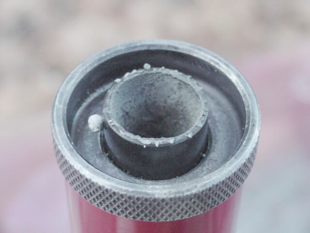
Loki 29mm 2-grain motor casing


This casing is smaller but otherwise similar. It uses a different method for the thrust ring - an external groove
is turned into the casing and a different kind of snap ring is fitted into
it. Seems to me this should have been placed below the nozzle ring
groove
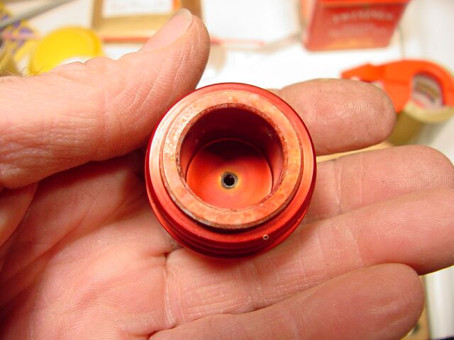
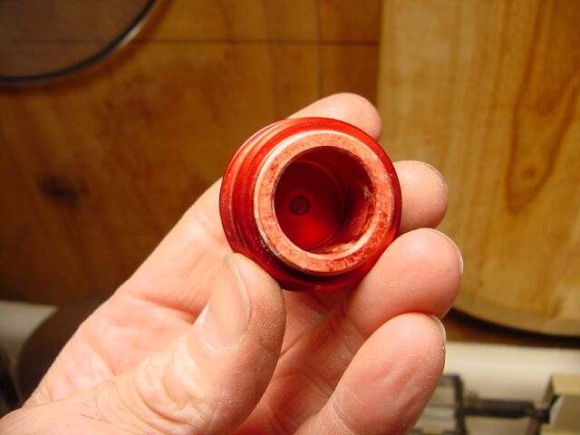
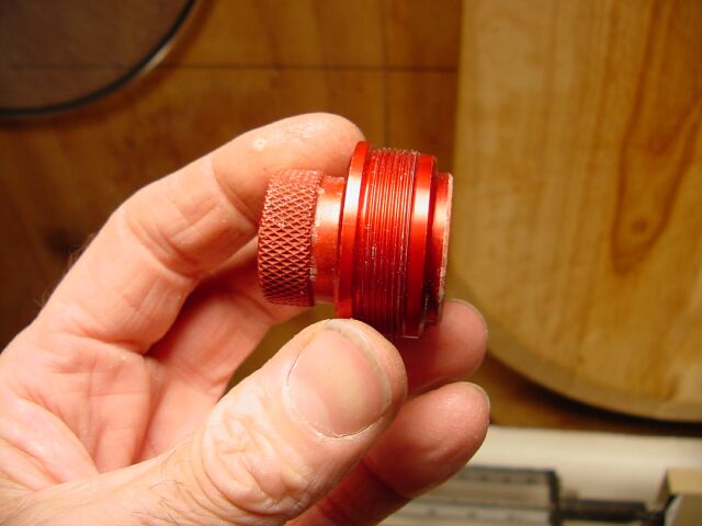
Aerotech - type header.
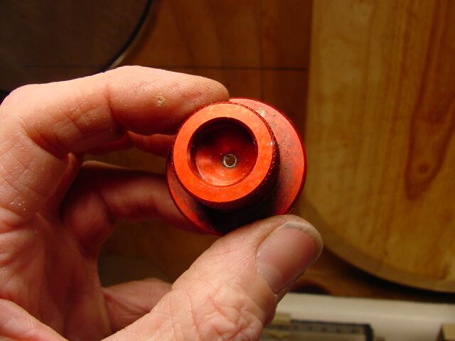
This head-end design provides for a burn-through
delay grain which fits in the 7/8 inch recess. It is a cyliner of propellant-like
substance which burns after the propellant has expired. It is secured
with an O-ring that (usually!) prevents blow-by. Check out my first
TRA Level 2 launch attempt for an example of how it can fail!


Note that if candy propellant is used, it may need to be a longer grain than
the 7/8ths inch provided here. The top en
The Aerotech nozzle design is more complex, and relies on the
propellant charges to keep the nozzle in place.
If you want to try it I'll
be happy to supply more photos.


Here are some other pages that might help:
Loki Research - makers of the blue motors above. New page on the 38mm motor shows how delay grains might be installed, using a whole bunch of O-rings.
Animal Motor Works - Makers of commercial motors and reloads of similar design. Here is their hardware page. Also, their loading instructions have some clues on how things go together.
Woody's Pro-X Hardware - makers of the "Purple Woody" rocket motor casings. Very similar to Loki but with two O-rings.
As far as casing thickness and strength go, I would refer to Richard Nakka's pages on that topic. He has a spreadsheet on his software page
that allows one to input the material properties, casing diameter and wall
thickness, whereupon it will list the casing burst strength and safe working
pressure.
Couple that with a few of his tables that give pressure at any given Kn ratio, and my little KnCalc program that plots Kn ratios, and one can develop a rocket motor that with (probably!) work on the first try.
I hope this leads to some motor casings! Please let me know if more is needed.
Jimmy Yawn
jyawn@sfcc.net
Jimmy Yawn
jyawn@sfcc.net