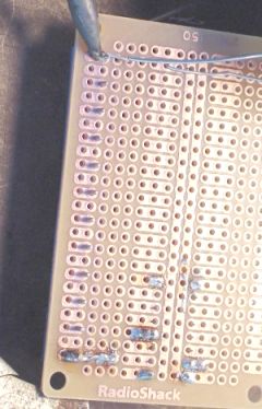
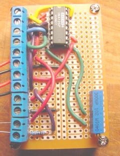
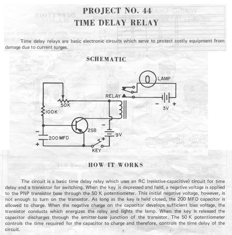
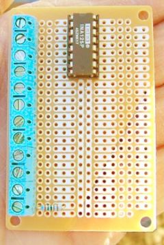
Timers for Rocket Ejection.

I.  Types of timers:  Discrete Component vs Integrated Circuit

A.  Discrete Component refers to indivitual transistors, capacitors, resistors and other parts, each of which has a single function.  Such timers are usually triggered with a break-wire.

B.  Integrated Circuits include several discrete components in one IC package, pre-configured to serve a particular function.   IC timers may be triggered with a break-wire or with a G-switch, depending on the IC that is used.


II.  Getting it together - some options:

III.  Turning it on:  Two more options.


1.  Break wire, or equivalent.  Many timers use a break-wire or some other external "switch" to start timing when the circuit is broken.  

a.  This can be a thin strand of wire, like one of the copper "hairs" from a section of lamp cord, which is wired to the altimeter by terminals somewhere on the rocket body and anchored to the launch stand at some point.  Rocket takes off, stand holds the wire back.  Wire breaks, circuit is interrupted, and timer starts timing.
Possible downside:  Too strong a wire could hold a small rocket back.  Dangling wires could contact each other in flight, restarting the countdown and making for late ejection.

b.  I've heard of those that ran the current through a section of solder which went under the rocket nozzle.  Exhaust heat melts solder, provided that the solder stayed in place.  Actually that much heat could melt copper almost as easily.  
Possible downside:  slow-igniting motor could melt the solder a few seconds before liftoff, making for early ejection.

c.  Another is to put a reed switch in the rocket, and have a magnet on the launch rod hold it closed.  Rocket leaves rod, switch opens, timer starts timing.  
Possible downside:  Bumping the magnet away from the rocket could cause pre-launch ejection.  


d.  Some folks mount an audio-type earphone jack in the tail end of the rocket, facing down.  A tethered plug is inserted in the jack, keeping the circuit closed. The plug is tied to the launch stand, so that when the rocket takes off, the plug is jerked out, the circuit broken, and the timer starts counting down.  
Possible downside:  these jacks are not designed for high acceleration, so their reliability under rocket conditions must be monitored.  Also, exhaust products are corrosive, and may cause flaky connections with any electrical connector mounted near the motor.  


e.  Terminals on the side of the rocket are connected with a strong wire by small alligator clips, like those used for Estes ignitors.  Wire is mounted firmly to test stand, so that when rocket takes off, the wire stays behind - clips slip off the terminals, breaking connection and starting the timer.  
Possible downside:  Bumping one of the clips could start the timer.


Obviously, the rocket needs some kind of on/off switch mounted where it can be actuated on the pad.  The timer is kept OFF until the last minute, switched on just before you walk back to the launch control area.  

There are several other alternatives, no doubt some of them already occur to you.  But the downside of the break-wire is that it requires something external to the rocket.  

2.  G-switch.  This is an internal switch that senses the motion of the rocket to trigger the timer.  G-switches can be mounted on the circuit board, so that everything is inside the rocket.  One can buy such switches - Perfectflite (listed below) has one for $8..  

Many rocketeers will take a common micro-switch, epoxy a weight to the lever, and orient it in the rocket so that when the rocket takes off, the lever closes the circuit, starting the timer.  

The g-switch is more often used with the 556 dual-timer chip.  This chip allows a single "pulse" or momentary circuit closure to start the timer sequence going.  

Possible downside:  Dropping the rocket, or moving it abruptly, could start a g-switch timer counting down.  The more sophisticated timers often have internal protection against such events, but caution is still advised.  

Again, an external switch is required, so that the timer can be powered-up after it is on the pad and ready to go, and inertial events are unlikely.


IV.  Discrete Timer: The basic idea:

A.  Schematic from Radio Shack 150 Project kit (circa 1972)
Click picture for larger version with desescription.

RC-timer from Radio Shack kit

The Resistance-Capacitance timer circuit works as follows:

1.  Battery (9V) supplies current to a capacitor (200 MFD), which holds electrons, gradually building up a static charge.
2.  Resistors (100K and 50K) restrict the current, slowing down the buildup of electrons in the capacitor
3.  One of the resistors (50K) is adjustable (potentiometer) allowing user to change the rate at which the capacitor fills, thus adjusting the length of the delay.
4.  Transistor (2SB) "reads" the the voltage in the capacitor, and when it reaches a certain (trigger) voltage, "opens the gates" and lets the current flow freely.
5.  Current through transistor actuates a relay (1) which closes a circuit between battery (3V) and e-match (lamp) firing the ejection charge.

(1) Use of a relay is not recommended in rocketry timers.  The relay is a mechanical device that could be actuated by acceleration, heavy vibration, or rough handling.  A solid-state device such as MOSFET (Metal-Oxide Semiconductor Field Effect Transistor) should be used instead.  


B.  Here is a discrete-component timer designed for rocket ejection use:

Johnny Dyer - One-ounce discrete component timer

(Click here for an alternative link to same description)

Johnny Dyer's One-Ounce Timer

Johnny's page contains schmatic, plans, and parts list.  

This offers three options:

1.  Get the parts yourself, figure out how they go together from the schematic and diagrams, and put it together with either an electronics project board, or by making the printed-circuit board yourself.  Kits for etching your own PC boards are available at Radio Shack and other electronics suppliers.  

2.  Buy the printed circuit board from Johnny, and get the parts yourself.  This saves the trouble of wiring the project board or etching your own, and reduces the probability of assembly errors.  

3.  Buy the whole kit from Johnny.  This could prevent hours of shopping.    


V.  An aside:  Project Boards


Project boards come in a couple of flavors... one type is just a grid of holes with solder-pads, so that you can attach anything to anything else either with a solder bridge or a jumper wire.  

The other "flavor" is a board that is designed to facilitate the use of an IC chip.  This is the type I used in the INA125 amps, and would be better for use with the 555 or 556 IC type timer.  (The boards shown here are being used to assemble the INA125 amp, not a timer.)

      
IC-type gridboardIC Gridboard backIC-gridboard with more components
Here is one with a few parts on it.  The backside, showing copper traces.  
Note that solder can be "bridged" between adjacent spots to connect them electrically.  
Fully populated board.  Note wires used to run current from one spot to the other.  Wires can be run on the solder-side too, but I prefer to put all my wires on top where I can see them all at once.

The white marks show which holes are electrically-connected to each other by the copper traces on the other side of the board.  Note that the middle holes are all connected vertically.  I use them as "ground" on the amplifier.  The sets-of-three on either side are designed to accommodate the width of a standard IC package.  The IC pins are is soldered to the innermost holes, then there are two other holes allowing one to connect the pin to other things on the board.  

I like to use the IC sockets, which are soldered to the board, then the IC inserted.  They are cheap insurance that one does not damage the IC when soldering.  They also make it easy to pull a "bad" chip off the board and substitute a "good" one.  This is valuable for trouble-shooting, as the chips are rarely "bad," it's usually a wiring error, dead battery, or some other goof that makes it not work. But being able to switch out the IC is a good way to determine that it is not the chip at fault so one knows to look for other errors.

This particular board should work, but is larger than necessary for the IC timer.  Radio Shack has smaller ones, or the larger ones can be cut down as needed.


VI.  Integrated Circuit Timers

A.  555-based timers:

1.  Scott Fintel - $5.00 timer  Scott sells kits to build this timer, which are only $10.00.  This is a great deal, and might be my first choice.  
Scott's design is uses the 555 timer and thus requires a break-wire to start timing.

2.  Here is a Tutorial on the 555 timer - what it is, how it works, how to make it work - breadboard experiments.  It does not show how to make an ejection timer, but is very helpful in understanding how these timers work.  


B.  556-based timers:

The 556 IC has two 555 timers on the same chip.  This allows one timer to trigger the other, making the use of a G-switch feasible.

1.  Robert Galjeis - Tiny Timer  Robert's timer uses a 556 dual timer, thus it can use a G-switch to sense liftoff.  
     So it is all self-contained in the rocket, no break-wire is needed.  

2.  Richard Nakka also has a design for a 556-based ejection timer, using a G-switch.  His design is based on Robert's but adds a safe/arm switch to allow on-pad testing of the timer, and an e-match continuity test LED.  Richard's timer is triggered by a mercury switch, which detects the sudden deceleration at motor burnout, and starts the timer then.

3.  Perfectflite Mini-Timer - These are pre-built, fully assembled and almost-ready-to-fly timers.  If money were no object and I just wanted a timer that worked, this would be my choice.  In fact, that's what I did earlier this year when I wanted a back-up timer for the Sugar Rush.  Concerned that I might have another core-sampler, I added a timer so that if the altimeter failed, the timer could save the bacon.  Prices range from $24.95 to $42.95.  These timers can be actuated by either break-wire or G-switch, your choice.  

I opted for the MiniTimer3 with G switch because it's all there, self-contained and complete.  Well, almost complete...I still have to mount it in the airframe, wire it to an external switch to turn it on, hook it to a battery, and wire it to the e-match.  But I don't have to worry about a break wire or adding a G-switch, as the switch is already on it.  

I am sure there are many options beyond those presented here.  So if none of these seem likely to meeet your needs, please let me know and we can consider others.


VII.  Safety concerns

1.  Power-on surge.  Any new timer (or other recovery device, for that matter) should be tested with non-pyrotechnic loads several times before it is used with a real charge.  Fear is that the surge of power that occurs when the switch is flipped may trigger the counter.  It should be tested with Christmas-tree bulbs or a voltmeter to ensure that current does not flow to the pyro output either at power-up, nor after the selected timer interval.

For extra safety, one could place a shunt or switch between the timer and the e-match, so that any power-on spikes could settle down before the pyro charge is brought into the loop.  

2.  Verification.  The simplest timers do not contain circuitry to verify their condition.  Commercial timers and altimeters usually emit a series of beeps after power-up, signaling to the user that the e-match and break-wire have continuity and that the battery is supplying adequate power.  Richard's timer has a continuity-test LED for the e-match.  But simple timers do not have these features, requiring that the flyer must check these conditions manually.  


Jimmy Yawn
jyawn@sfcc.net
5/7/07