Delay Grain
 for Rcandy reloads in
 Aerotech-Type motor casings

Delay Grain


The problem:  Effecting motor ejection with homemade sugar-propellant grains.  

The blatantly obvious answer:  Use a string of propellant to continue to burn after the motor is exhausted.  Rcandy burns very nicely so, like a thick fuse burning from one end to the other.  

The paranoia:  How on earth can one contain the pressure of a working rocket motor and keep the gasses from blowing by to ignite the ejection charge prematurely?  

The acceptable level of leakage is easily determined:  None.

The acceptable level of failure is also easy to figure:  None.

Failed ejection is, in my opinion, the most dangerous feature of amateur rocketry.  How fast does the airframe come down, streamlined, from say, 2000 feet?  What is it's energy at that velocity?  And just where is it going to land?  The possibility of CATO is trivial compared to this danger.  This is why I tend to cant the launch rod away from the crowd, even if it means less altitude and a longer walk.

In truth I have been making burn-through motor ejection of this sort for quite some time in single-use motors.  Examples include the model rocket motor, the cast-nozzle aluminum motors, and some of the PVC motors.  In these, a slug of recrystallized KN/sucrose is made to fit the head-end of the motor with a little clearance, and once cooled it is glued in with 5-minute epoxy.  In the PVC motors, an end-cap is glued over the grain as well, since epoxy does not stick very well to PVC.  A hole is drilled in the cap to let the flame through to the ejection charge.  

At first these delay grains were unreliable.  The grain would often go out during flight, for no apparent reason.  I assume this to be due to the radical drop in case pressure when the propellant charge was exhausted.  So this method was not used for anything serious.

Then I discovered red iron oxide.

The addition of this catalyst serves to maintain the combustion of the delay grain even when a traumatic drop in pressure occurs.  In perhaps a hundred such tests, none have spontaneously extinguished.  Not one.  

Problem solved.  

"For every problem there is a solution."

You've heard that, right?  Many times, no doubt.  But I am convinced that for every simplistic statement like that, the converse is equally true.  This solution creates other problems.

But I will set that one aside for the moment, and concentrate on making a delay grain that does not leak, but can be removed from the motor after it has fired and quickly replaced for another firing.  I had envisioned gluing a slug of propellant directly into the header recess, but getting the residual glue out could be a problem.

The Aerotech procedure

I have used my Dr. Rocket casings with Aerotech reloads twice.  Both times were for TRA certification attempts.  I recall the delay grain assembly process as a fiddly sort of thing involving an o-ring around the delay grain, then a cardboard sleeve around it, a funky inside sleeve, a secret handshake and a wink at the barmaid.  Apparently I got it wrong once, resulting in early ejection and thus failure of my first Level 2 attempt.  Think I blinked rather than winked.

The Loki procedure

But the other day I had a revelation.  Looking at instructions for the newly-certified  Loki 38mm reloadable motors, I saw that the delay grain was wedged into its recess wearing a stack of O-rings, all the way from one end to the other..

Bingo!  Not only do I trust Jeff's designs, but this one just seems right.  Besides, it's something I can do myself.  It's cheap, easy, and quick.  Exactly my style!  I just need to find a suitable kind of tube that will fit into the bulkhead recess with a little room to spare, and get some O-rings that will take up that spare room plus a hair.

Looking around the scrapheap, I found a piece of 1/2 inch CPVC pipe, commonly used for hot water plumbing in these parts.  It was a leftover from the outdoor shower I put in a few years ago.  The shower is already kaput, victim of a freeze.  (Yes, it does freeze here - two or three times each year!)  This is vintage pipe.  I scraped off most of the dirt, and found that it fit into the delay-grain recess with a little room left over.

Dimensions

CPVC pipe:
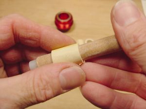
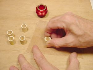
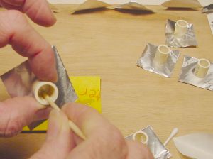
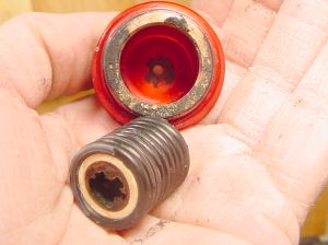
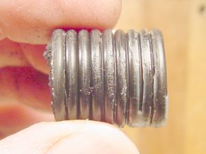
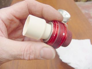
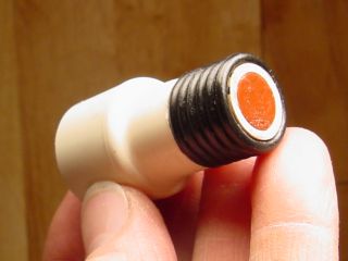
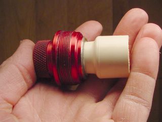
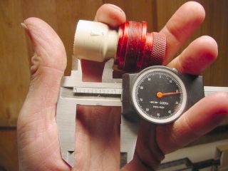
Outside diameter:  0.625 (minimum) by 0.63 (maximum) = 0.6275 inches average OD  (Roughly 5/8 inch diameter.)
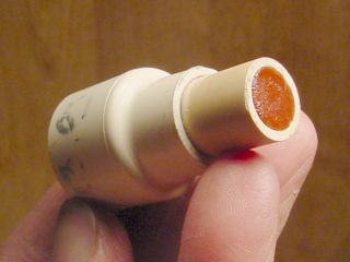
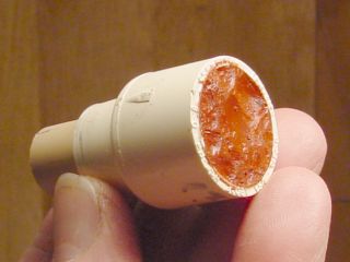
Inside diameter:  0.479 (minimum) by 0.489 (maximum) = 0.484 inches average ID (Just under 1/2 inch)
Weight:  3 grams per linear inch
Dr. Rocket motor-eject header:
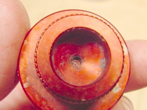
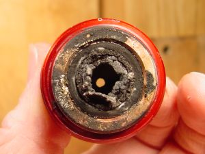
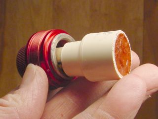
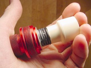
Recess diameter:  0.812
Recess depth:  0.871 inches
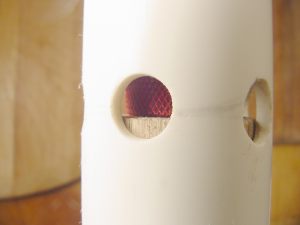
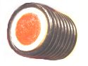
Burn-through port:  0.12 inches diameter

So (0.812 - 0.6275)/2 = 0.09225 inches clearance on either side
3/32 inch = 0.09225

13/16 inch = 0.8125 inch

So it looks like I need to get O-rings 13/16ths OD and 3/32 inches thick  I wonder if they exist...

Well they do!  And they are a standard size.  Even the local Tractor Supply store carries them, at $0.61 each.  That's a bit much, but I have to try this now so I bought all four of them.  

Since then I have looked back at the Loki page and the Aerotech instructions, and found that they are using the exact same size O-ring.  Well, well, well.  
And I got a zillion of them from McMaster-Carr for $2.94 per hundred.  (BUNA-N, McMaster Item # 9452 K26, AS568A DASH number 114)

So here is how it's done:


Sand Inside of CPVC tube  Sand Ends Flat  Cut pieces of aluminum tape

I cut a section of CPVC 7/8ths inch long, trued the ends, and cleaned it up.  Sanded the inside with 150 grit wrapped on a stick to get the roach eggs out and rough it up a bit.  Ends are rubbed on sandpaper laid on a flat surface.  Frilly edges are removed with a fingernail or a knife blade.


Squirt out some epoxy   Spread epoxy inside tube  

Cut off a piece of warmed rcandy   Roll Propellant into slug

One end of each tube is stuck to a piece of aluminum foil duct tape.  I like this tape because it seals well, but peels off fairly well.  

The inside of each tube is coated with a thin layer of 5-minute epoxy and a slug of warm, soft rcandy pressed in to fill the tube.  

Drop slug of propellant into tube   Press propellant with a dowel    Press propellant down manually
.
First a pencil, then a thumb are used to press the propellant into the tube.  The backing paper from the foil tape makes an excellent non-stick pressing pad.  

This propellant is a slow batch of rcandy that had been catalyzed with 1% red iron oxide to bring its burn rate up to 10 seconds per inch at 1 atmosphere.  It was allowed to cool and harden while I struggled to get the residual epoxy off my hands.  Epoxy is one of my most favorite glues, and one of my least favorite flavors.


Trim off extra propellant  

Often there is a bit of overflow.  That's OK.  I would rather have too much propellant than too little, and the extra is easy to trim off.  Probably wouldn't hurt to leave it on.  I'll try that when you aren't looking.

Covered with greased O-rings   Squeeze the delay package in header      

Eight O-rings are greased a bit and stacked on the delay grain.  Looks sort of like the Michelin man, doesn't it?  More grease is applied and the whole unit sliped down into the bulkhead recess.  Takes a bit of wiggling to get it all in, but it's not very hard.  Looks like I have room to insert one more O-ring, so I will!

Pack down O-rings with skinny dowel   All rings in

A crudely-carved stick is used to pack the O-rings all the way down.  

Top view showing propelllant peeping through    Funnel in some black powder    Pack Black Powder in Hole

On the other side, we can see the rcandy looking through the vent into the ejection-charge recess.  That is reassuring.  I will use a small drill-bit to clean out to fresh propellant just before adding the powder charge, and will press some of the black powder charge down into that little vent to make sure there is contact.

Cap ejection charge recess with masking tape    Cap of tape over ejection charge    Propellant Grain

The ejection charge recess is almost-filled with homebrew black powder and masking tape pressed over it.  I didn't bother to measure it here, as all I want is a nice smoky flash to tell me when the charge ignited.  And here is a gratuitous photo of a propellant grain.  Nice swirls, don't you think?


Vented Test Stand         

Now that I have a digital test stand, I want to get a thrust curve from every firing, no matter how trivial or redundant.  On second thought, I don't want to subject the electronics to the flash of an ejection charge or to the corrrosive residue.  So I make an extended motor mount which has vent holes and a wooden spacer to separate the ejection from the other stuff.  Hope it works.  


Ejection!

It works!  Click Here to see a video of this static test
(1.4 meg .mpg file, 10 seconds of video)

This test used a single inhibited grain, generating a progressive burn profile.  
Burn time was 1.48 second, delay was 7 seconds, ejection charge fired as hoped.  
Peak pressure would have been about 400 psi.  

Autopsy

At first glance it looks pretty bad, but in truth all is well.  We can see straight through the vent hole.  Pair-O-Pliers pulls Michelin Man out without a struggle.  

Burned through   Only the top O-ring is damaged   Delay grain covered with O-rings       

Does this seem like an extravagant use of O-rings?   It seemed like a waste to me too until I took this wad apart and realized that only one of the rings was damaged, the rest could be reused.  So I simply must adjust my thinking to know that only one ring is used to seal, the rest are used for support.  

The first one on the motor side got fried, no big surprise there, but the rest of the rings are pristine.  Well, they are covered with grease, but that's not an insurmountable problem.  I guess the one on the ejection-side might catch hell some of the time and would certainly require close inspection before reuse, but in all 6 of my tests so far it has been OK.  So even though 9 rings are used, only one is used up.


This load would have been just fine for my "A-Minus" airframe (the Ariel with some parts removed) sending it to about 800 feet, apogee at about 7 seconds.  But what if I used the larger motors?  I have 3, 4, and 6-grain casings of this size, and might want to send my rocket to higher altitude, which would require a longer delay, right?

Expect Longer Delays

KNO3/sucrose burns pretty fast, especially when catalyzed.  The maximum delay I have obtained so far was about 7 seconds.  This would be adequate for some low flights, but I would like the option of going higher.  

Since the bulkhead recess is a fixed length, the delay element cannot be lengthened and stay inside it.  So a slower-burning composition seems called for.  But if rcandy delay grain is not catalyzed with red iron oxide it may go out causing failed ejection, danger to observers, destruction of airframe, and public humiliation.  Bummer.

So I tested one today with a "duplex" delay grain, two different propellants in the same delay-grain tube.  The first section to burn is catalyzed rcandy.  This is deep enough that it will still be burning when the propellant grain burns out, but shortly after that will transition to an overcooked, uncatalyzed propellant which burns about 18 seconds per linear inch at 1 atmosphere.  Such slow propellant often goes out by itself when burned in open air, but I've found that containing it in a tube tends to prevent self-extinguishment.  

The first part of this delay grain is expected to burn really fast, as it will be burning under motor operating pressure.  Web thickness for the propellant grain is .4435 inch, and since it is an uninhibited grain, the effective web thickness will be half that.  So I expect the first 0.2218 inch will be gone after 0.7 seconds or so, when the propellant grain is exhausted.  Maybe a little more thatn .2218 inch will be burned, since the delay grain is catalyzed, the propellant grain is not.

That will leave 0.29 inch of catalyzed propellant remaining.  I expect that it will burn at its 1-atmosphere speed of 10 seconds per inch, which would be 2.9 seconds.  Hey!  I did that math in my head!  Am I good or what!

Then the flame will transition to the slower-burning overcooked uncatalyzed rcandy, all 0.392 inches of it, which should burn at 18 seconds per inch, translating into an additional 7.056 seconds of burn time.

So the totals are:
0.7 seconds during motor burn, first .2218 inch of delay grain is burned at motor operating pressure.
2.9 seconds catalyzed burn, remaining catalyzed propellant will burn at the rate of 10 seconds per inch.
7.056 seconds uncatalyzed burn, 0.392 inch of uncatalyzed propellant will burn at 18 seconds per inch
= 10.656 seconds from ignition to ejection.

Note that "ignition" may not be the moment when the ignitor fires, not necessarily when the propellant grain gets all lit up.  Since there is a bit of ignitor lag time in my motors, a second or so of the delay grain might be consumed before the motor fires.  Guess I had better start working on faster ignition.  Or at least more consistent.  

So here is the static test of this motor:

 
Click Here
to view a video of this test
Modem users beware:  3.2 meg file for about 12 seconds of video.

 
Click the graph to view an Excel spreadsheet analyzing this test

Performance was pretty good, except for that funny little shelf before the motor finally ramped-up to operating pressure.  Ejection occurred 9.9 seconds after full thrust was achieved, within a second of the predicted ejection time.  The difference could be accounted-for by the faster burning of the catalyzed portion of the delay grain during motor burn.  Or maybe not.

There was 1.4 seconds ignition lag, so total time from ignitor firing to ejection was 11.4 seconds.  If I assume that the delay grain was ignited by the ignitor flash, the delay is actually a little longer than predicted.

This is a usable delay, and could be used for a flight motor.  Of course, one would have to tailor the motor to the airframe or vice versa, but this technique seems to offer good options in that regard.

The Dangling Grain

But why does the grain need to sit entirely within the header recess?  What about making it a little longer, so that it extends down into the propellant area a bit.  Then one might drill the grain core at that end to make room for the delay grain.  This is a novel design, so it would bear some testing.  Just so happens that I like testing!

So let's say the head-end grain had a 3/4 inch diameter core which tapered to 3/8 inch about halfway down the grain.  That would allow the extended delay grain to extend itself into the top propellant grain.  It would also create more surface area at the head end, which would be funnelled somewhat through the narrower core down below.  And it would burn out more quickly up there, creating a somewhat regressive burn profile.  Perhaps this could be countered by using longer grains than the optimal Bates length.  

But why go to all that trouble?  It would be much simpler to omit one grain, lengthen the others a bit and give the longer delay element some headroom.  Aerotech grains are a little shorter than the optimal Bates length anyway, so making them longer might yield a flatter burn profile.

So I will try it.

Long, Dangling Delay  

Long delay is full of catalyzed rcandy, burning at 7 seconds per inch at one atmosphere.
This is used in a 38-480 casing with two long grains average lenght of 3.3 inches each.  

Propellant grains are inhibited with an experimental inhibitor which didn't work very well.  Note funny curve.  

Movie of static test
Click Here for a movie of this static test.  
(Warning:  2.1 megs of download for 8 seconds of video)


Spreadsheet analyzing 12-19-04B
Click Here to view an Excel spreadsheet analyzing this test.

I expected a progressive burn, but not that progressive!  So much for my radical inhibitor idea.

But this provided an inadvertent test of the delay grain containment capability - it held OK despite a maximum case pressure of around 1000 psi.

You might notice that ejection occured only about 6 seconds after thrust began.  This is far shorter than anticipated.  

A possible clue:  Note that the CPVC tubing is completely burned away on one side.  I expected it to be scorched, but not burned all the way through.

Ugly Burned-away pvc tubing    

Makes  me wonder... PVC is used as a fuel grain in some hybrid motors, right?  Perhaps it becomes a fuel in the hot, high-pressure, oxygen-rich atmosphere of a motor casing?  Duh!  Guess I need to protect it some!  Or maybe just find a slower-burning delay composition that won't go out and use the shorter delay grains.

Another try

This one burns a single 3.6 inch uninhibited grain in the 38/480 casing.  Thus the casing is only half full, but the uninhibited nature of the grain means that it will develop approximately the same thrust and pressure as yesterday's test, albeit for a shorter time.

The delay grain is 1.5 inches long, and made with two propellant compositions.  The first .75 inch is rcandy catalyzed with 1 percent red iron oxide to prevent blow-out.  It burns at 7 seconds per inch at one atmosphere.  The last .75 inch is medium-slow uncatalyzed rcandy, burning at 13 seconds per inch at 1 atmosphere.

So the prediction is that the catalyzed propellant will burn about half its length during the motor burn.  0.375 inch gone in 0.6 second.  The rest of the catalyzed propellant will burn up in about 2.625 seconds, and the uncatalyzed propellant will burn for 9.75 seconds

Total delay from ignition onward:  (0.6 + 2.625 + 9.75) = 12.975 seconds.

12-20-04B Test Firing
Click Here for a video of this test
(Beware:  3.7 meg download, .mpg file, 15 seconds of video)


12-20-04B Spreadsheet analysis
Click Here
for an Excel spreadsheet analyzing this test

Good burn, generating about 150 N-seconds of thrust in .58 second.  The delay worked well, firing its charge 12.36 seconds after the first thrust occurred. Only about 1/2 second shorter than predicted.

PVC tubing was burned away much like the previous test.  But it must have held OK while the motor burn progressed, or else the delay would have been much shorter.  I think we are getting somewhere.  

 This is a much more reasonable delay for many of my planned flights.  I just hope it can be replicated.  Do we hear another test coming on?

More to the point, it is very much desired to get these paramaters in the bag so that delay grains can be constructed for any given flight, and the delay time predicted with a good degree of accuracy and reliability.  Today's test was good.  There must be many more.


More!  Duplex delay grain

In rummaging through my PVC parts, I came across a CPVC coupling, used to adapt 1/2 inch slip-fit tubing to a larger size.  It made me think about using a larger delay grain inside the motor casing.  This one was threaded and had hexagonal sides which did not fit into the 38mm casing, so I went out to seek some that would fit.

These are 1/2 inch x 3/4 inch female/female CPVC couplings.  They were $0.26 each, if I remember correctly.  I bought a handfull.


Short pieces of 1/2 inch CPVC tubing are cut, anywhere from 7/8ths to 1 inch long.  The length is not critical.  One end is trued up with sandpaper, the other one can be rough, as it can go inside the coupling where a little irregularity doesn't matter.


Short pieces of 1/2 inch CPVC tubing are cut, anywhere from 7/8ths to 1 inch long.  The length is not critical.  One end is trued up with sandpaper, the other one can be rough, as it will go inside the coupling.

A bit of cement is spread on the rough end of the tubing, and it is inserted a short distance into the coupling.  I immediately press this firmly into the Dr. Rocket header, to push the 1/2 inch tube into the coupling exactly the right distance.  


The 1/2 inch side of the coupling is tapered a little, and the mid-part of its taper happens to fit snugly into the Dr. Rocket delay grain recess.  Using the header as a jig ensures that the end of the tubing will reach the far wall, and that the coupling will reinforce its position by contacting the shoulder of the recess.

The assembly is removed from the bulkhead and any excess glue wiped off.  It is allowed to dry for a few minutes.


Then the CPVC assembly can be packed with delay composition.  In this case it is catalyzed rcandy.  The extra length should give plenty of delay, even though the stuff burns fast.  As above, the casing is sanded a bit to rough it up, coated on the inside with 5-minute epoxy, and warm propellant pressed into place.  Not illustrated here, but it is sealed with foil tape to keep it fresh and dry until loading time.  


Six O-rings are smeared with my favorite grease and placed on the skinny end.  The bulkhead recess is lubed a bit too, and the delay grain pressed home.  


The Superman act is a fake.  I usually do this on the counter and press down with both hands.  Here I am holding the camera in one hand and squeezing with the other, too lazy to set up the tripod.

Yes, you still need to install the O-ring that seals the forward bulkhead in the casing.  But it slips over the large delay grain easily, so that is not an issue.

This elephant grain extends 1-1/8th inches into the motor casing, taking up some of the propellant space.  So I just use a longer casing, leaving room.  And since Aerotech-type grains are a bit on the short side, I can use the bit of extra room to make them the ideal Bates length, or a little longer.  The wide delay grain also contributes a bit as an end-burner, so the space is not completely wasted for thrust.  

In the 5 tests of the duplex design so far, "all" have worked quite well.  One exception - in the first test the delay grain burned all the way through but did not ignite the ejection charge.  It is thought that the charge separated from the delay grain due to vibration from firing.  More care has been taken to ensure positive contact..  The delay time has varied a bit from what is predicted, but are generally within the "OK" range for launch, so that remains an issue for further study.  


Jimmy Yawn
jyawn@sfcc.net
Recrystallized Rocketry