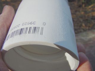
Nose Cone
Made from posterboard
| Zippy-Style Nose Cone Made from posterboard |
|
 |
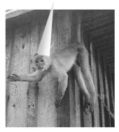
Here's where we are headed. It is, indeed, a
cone. You might scoff and say that a cone is not a very efficient way
to begin a rocket. And you would be correct. There are many
shapes that create a better laminar flow than a true cone. But with the kind of flying I do, the difference should be small. My Quantum Tube airframes are not recommended for Machbusting anyway. The cone is easy to make, can be done by hand with ordinary tools, and is thus very cheap. Besides, doesn't it bother you a little that the thing called a nose "cone" isn't? Where is the truth in our advertising, hunh? And look at this happy guy. His rocket has a CONE on the front end. How handsome! The rocket, I mean.... |
 Graph courtesy of Hans Olaf Toft
|
But there are some other pages dealing with nose cone design considerations, and they are not as complementary to the cone cone. Model Rocket Drag Analysis using a Computerized Wind Tunnel Thanks to Scott Fintel for suggesting that one. David Stribling - Ogive Nose Cones - mathematical definitions The Descriptive Geometry of Nose Cones - G. A.. Crowell, Sr. (Word document) WikiPedia - on Nose Cone Design. This description appears to be an adaptation of Mr. Crowell's work. Recently, Hans Olaf Toft has simulated prospective nose cone geometries for the Sugar Shot to Space: Nose Cone Drag Study for the SStS Rocket and guess what? The true cone is dismal only in the transonic range. Note the plot line (blue) for the Power 0.75 nose cone. It looks like one of the better ones for this high-performance rocket. More on that later. |
 |
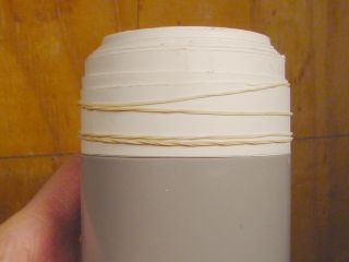
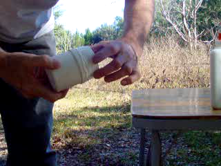
Two sheets of posterboard are required to make this nose cone, and sometimes part of a
third. Most of one sheet is used to make the cone itself, the
rest made into a base A few PVC parts serve as the foundation for the base, and also make it a strong, closed container which could serve as housing for electronics or non-vertebrate animals. After shaping, the cone will be strengthened with coats of epoxy on the inside and a layer of fiberglass on the outside. The fiberglass may not be necessary, but I think the cone will hold up much better with it. |
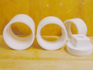 |
Four PVC parts are used to make up the base. They are 2-inch (nominal, inside diameter) Schedule 40. The parts will be assembled into a single unit, which will be padded on the outside with posterboard to make it the right diameter to fit the 3-inch body tube. I am using PML 3-inch diameter "Quantum Tube" but I am sure this could be adapted to other sizes with minor adjustments. Outside diameter for these fittings runs from 2.7 to 2.75 inches. They can be ground down to a uniform size, or strips of posterboard used to build them up to a uniform diameter. |
 |
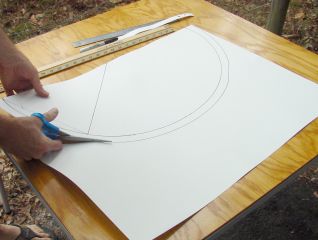
The cone itself starts as a semicircle cut from a sheet of posterboard. In making the model rocket cones, I used the whole 3x5 card, then trimmed off the excess. But this posterboard is thicker and there is a lot more of it. It is much easier to work if the excess is cut away before rolling. |
 |
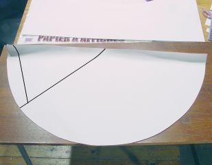
Here is a more precise way to mark and cut. Mark the
center point of one of the long sides. Trace a semicircle of 13
inch radius from the center all the way from one corner to the other.
This will be the approximate baseline of the cone. Trace
another semicircle 14 inches radius, or you can just imagine a traced
line and cut roughly an inch beyond the first line.
The extra inch provides a little room for error. Make a mark 1 inch from the top-left corner, 13 inches from your center point. Use a ruler or two to find the point that is 10 inches from your mark and 13 inches from the center point. Draw those lines. The "Target Line" from the center to the 10-inch mark will be important later - it is the masking line, and guideline for the rolling operation. |
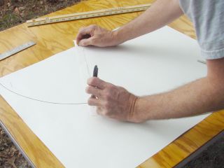 |
Here I am using a strip of posterboard with two holes 13 inches apart, a push pin holds one end while a marker draws the baseline semicircle. |
 |
The second semicircle does not have to be drawn, but I've done it here anyway. Using that strip compass is kinda fun! And it illustrates that one should cut a little bit away from the intended baseline - better to have the sheet too long than too short. |
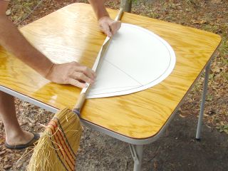 |
The straight edge is rolled around a dowel or other round
thing. Size is not critical, but it should be small enough to
give the board a good, tight curl. This broom handle is about an
inch in diameter, which is a good size. Pre-rolling the beginning and ending edges will make rolling the cone much easier when the time comes.... |
 |
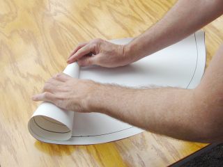
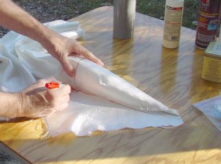
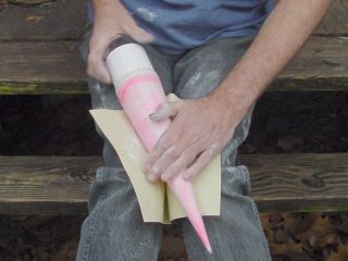
... and it's coming pretty soon. But
first we need to pre-roll the posterboard to convince it that it wants
to be a cone. Remember the "pinch point" marked an inch to the left of the center point? Well that's where I'm pinching it now. This is where the roll should start. The tip will not really be a tip, it will be a tiny opening, and this point is where it will start. The opening will be plugged later. |
 |
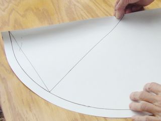
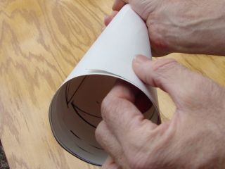
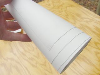
Curl the upper edge over and down so that the
edge hits the target line, the one you can
see between my two hands. It won't match up exactly, since
the pinch-point is not at one end of the line. No big deal, just
roll to match up at the bottom, best you can. The edge being rolled over with my left hand... that edge should meet up with the target line, perhaps to overlap it but only by a hair. This establishes the diameter of the cone at that end This roll isn't critical - it's just for practice and persuasion. But when the glue is sprayed, it must be repeated in one stroke, and accurately - the spray glue is a contact cement and it's not very forgiving. Once it is stuck, attempting to reposition is futile. It just tears up the posterboard. |
 |
This roll is going pretty well. Note a little spiraling out at the lower end of the cone. That much spiraling is tolerable. If it were to spiral out too much, then pinch point might need to be moved nearer the center of the posterboard. If it were to spiral IN too much, the pinch point should be moved further from the center point. |
 |
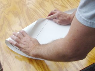
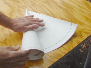
This is good enough. There is a little spiral going
inward, but it is within an inch of the edge. We will trim away
at least an inch, so this is of no consequence. What is of consequence is the next roll. Glue will be used. |
 |
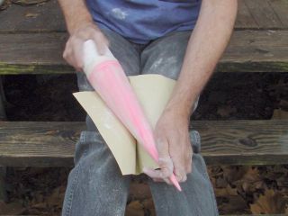
Unrolled, the coneboard is masked to the target line with
green tape and a Pep Boys ad, and sprayed with 3M Super 77. Can't
see the spray? Right! This is a setup. I don't want
to spray on the table, the overspray would make it really sticky for a
long time.
So I took the whole thing to another spot to do the actual
spraying.
I strongly recommend doing this outside. Spray this stuff
in a room with other folks and you could become very unpopular. One light coat is enough, but I generally hit the edges twice just to be sure. Super 77 is the best glue I have used for this purpose so far. 3M "General Purpose 45" is OK, but not quite as tacky - it's a little more forgiving, but not as strong. |
 |
What's wrong with this picture? I blew it with this roll, and started at the center point of the straight edge, not the pinch point. The cone is going askew. And this time with glue. Oh well. If that's the worst mistake I make today, I'm doing better than average. Good thing posterboard is cheap. |
 |
Here is a good example of a bad example. The cone rolled up on itself, perhaps beyond the point where the base will attach. Now this one could be used, as much of the paper will be sanded off anyway. But since I'm doing this for show I'll make a prettier one before continuing. |
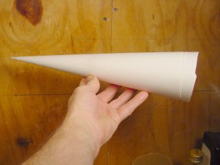 |
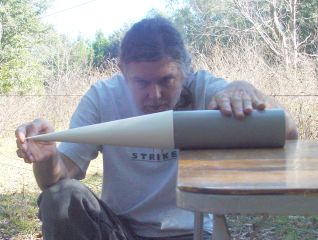
Ta Daa! A nice cone. Reminds me of my school
days. It's a little irregular at the bottom, but that's OK because
we intentionally made it a little larger than needed. That
irregularity will be trimmed off with scissors. But by itself, it won't fit our airframe very well, will it? It needs a base that will slip inside the body tube. So we are going to make one. First, a little plumbing. This base will be built around some PVC fittings. Not only does it give us something cylindrical and sturdy to roll the posterboard on, but it can hold a loop to connect a shock cord, AND possibly a mount for electronic gadgets. |
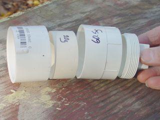 |
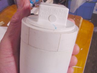
The parts are, from left to right:
|
 |
Here is a little problem that's gotta go: The Boss. I'm sure he has a function somewhere, but not here. He is just in the way. |
 |
A few seconds on the belt sander takes care of this boss. How about yours? It also roughs up the surface of the PVC, to better accept the glue. If you don't have a belt sander, a disk sander for the electric drill should do. That is a very handy thing. If power tools were not available this operation could be done with a file, rasp, or sharp rock. |
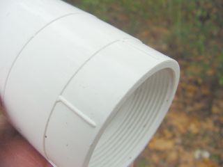 |
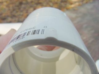
Here is another little problem. These ribs prevent
the posterboard from sticking evenly. I ignored them on the first
base I made, filled in the gaps with epoxy and it worked OK. But on this one I will do it differently. The ribs are ground off.... |
 |
... and 3/4 inch wide strips of posterboard glued in the
recess to build it up to the diameter of the rest of the fitting.
I need to add one more short section here, to build it up a
little higher than the PVC, so I can sand it all down flush. Love
that belt sander. |
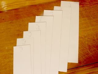 |
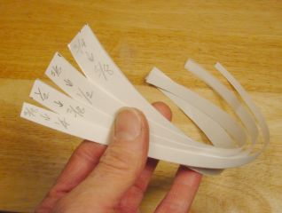
Getting ready for the big buildup. I know from a
previous attempt that it will take 8 strips of posterboard to build up
the PVC fitting so that it is snug inside a 3-inch Quantum tube. The posterboard measures 0.010 inch thick If these seem a bit irregular, you are right! I have cut each strip with a little taper. Here's why: |
 |
The first base I made started out with a square shoulder at the top,
each strip the same width. After rolling on a few, I
realized I would have to sand off a large amount of posterboard to make
a good glue-joint for the cone, which has a 12.5 degree half-angle.
It would seem that sanding this stuff on a belt sander would be quick and easy. It isn't. The paper clogs the belt immediately, and it sands very slowly. Good for control, but it takes a long time and a lot of belt cleaning. So the less sanding I have to do, the happier I'll be. Here is one of my previous bases. I started getting smart here by making the subsequent wraps shorter, in an effort to approximate the angle of the paper cone. I did not quite succeed, as you can see. I'll do better...starting now! |
| Each strip is 14 inches long, half the width of a sheet of posterboard.
They are slight trapezoids, with one of the short
sizes slightly shorter than it's opposite. The sizes are: 4 inches tapering to 3-7/8ths inch 3-7/8ths tapering to 3-3/4ths 3-3/4ths tapering to 3-5/8ths 3-5/8ths tapering to 3-1/2 3-1/2.... Well, all you "rocket scientists" have probably figured out the formula by now. |
 |
 |
Much better, wouldn't you say? My rolling was not
perfectly straight, so a little sanding will be required to make this
fit the cone flush. Alternatively, I could just use enough epoxy
to fill the gaps between it and the cone and not have to sand at all.
I'll try that on the next one. |
 |
The cylindrical part of this slug fits tightly in the 3-inch Quantum tube, so I go to the sander and take it down a little. Now the whole thing drops straight through the tube.... something is missing.... oh yeah, the flange! The little ringy thingy that makes the nose cone sit on top of the airframe, not fall down into it. Note that the PVC fittings are recessed a bit. I made the paper 1/2 inch longer than the PVC fittings, to maximize contact with the cone |
 |
So we will add a flange. A shoulder, if you prefer. Four more strips are cut, each 14 inches long, as before. The widest starts at 3/4ths inch wide and tapers to 5/8 ths, the next from 5/8ths to 1/2, 1/2 to 3/8ths, 3/8 to 1/4 and we are done. |
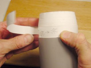 |
The base is inserted in the Quantum tube so that the taper starts 3/4ths inch above it. The widest strip is sprayed with glue, and the add-ons start. The tube provides a good guide for the lower edge, to keep it wrapped straight and true. We will not worry about the upper edge - it is becoming part of the taper, and will be sanded smooth once the glue is dry. These four strips build the tube to a slightly greater diameter than the OD of the Quantum tube. That's OK, the sander will take care of that too. |
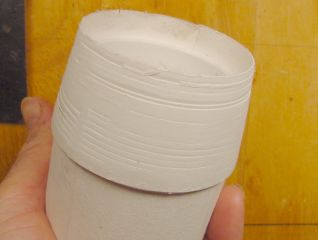 |
Glue has dried and it's been smoothed some on
the sander. The base is ready to
glue into the cone. How exciting! But it is getting late. Let's do that tomorrow. Better light. Better photos. |
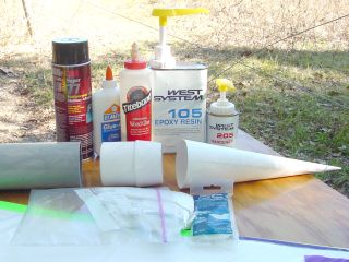 |
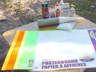
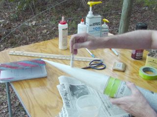
Yesterday was windy and rainy. Today is clear and beautiful. Here is the stuff, all my glues out on the table, the fiberglass cloth, and the parts. It's time to join the base and nose cone. |
 |
The tapered end of the base is smeared with a good coat
of Elmer's
Glue because I couldn't get the Titebond bottle to open. Glued
itself
shut, can you believe it. But Elmer's is fine, since the base has
been sanded to a taper which matches the cone pretty well. If the base had not been sanded to that nice taper, then epoxy would have been a better choice to fill the gaps. It also allows more working time, and might make a stronger bond. But I'm not sure - PVA glues like Elmer's and Titebond are pretty darned strong when used with porous materials like these. Either PVA or epoxy would be stronger than the posterboard, by a good margin. |
 |
The base is inserted in the cone as straight as my
eyeballs can see. Not very straight, as you can see. But then I slip it into a short section of Quantum
Tube and roll it on a flat surface,
noticing if the tip of the cone bobbles up and down. If so, I
move the tip
towards center and roll again. When the tip moves in a straight
line, I set it aside and let the glue do its thing. Click Here for a movie of me rolling this one around, and not getting it exactly right. (1.4 meg .mpg file, 15 seconds of boring video) |
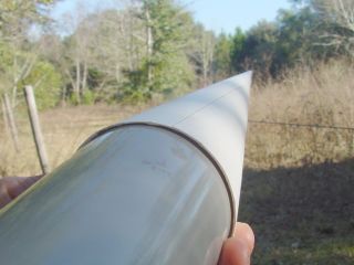 |
Glue has set a few minutes, so it can be handled.
The cone overlaps the body tube by just a little. This
overlap will be removed with the belt sander. If I didn't have a
sander, I might trim the cone more closely with scissors before gluing
it to the base, to reduce the hand shaping required. |
Jimmy,
I have not tried using the spray glue.
Others have and like it. The concern I have with using it for body tubes is
that might result in an inferior bonding of the epoxy/fiberglass to the
paper. If you are only using the paper as a form, that is no problem, but if
you have part of the structure on the inside of the paper and part of the
structure on the outside of the paper, then the paper and any other layers
of stuff, like spray glue, must be as strong as necessary or the structural
parts can come apart. By having a layer of epoxy and fiberglass on top of a
layer of spray glue on top of a layer of paper and then centering rings, etc
inside of the paper you end up with a strong layer that is connected to the
centering rings by two much inferior layers. If you use epoxy right on the
paper, it penetrates into the paper and the paper becomes a reinforcement
for the epoxy,
What I do (and it certainly did not originate with me - I saw it in the first videl that Dave Triano did for composite rockets) is to brush a thin layer of epoxy onto the paper or body tube and then just lay the fiberglass onto it. It works just the same as the spray adhesive, except the epoxy can penetrate the paper and stick to it much better. Anyway, that is my theory. It would be interesting to test it.
I don't like to wet down the fiberglass first either. It gets all over and the weight makes it harder to handle the glass cloth.
Feel free to use my comments. There are some better resources on the web for epoxying rockets. John Coker has a lot of stuff. West Systems has information that is for boats, but the techniques are really the same.
Steve
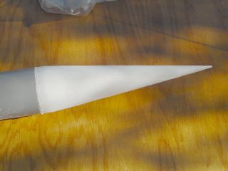 |
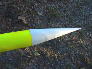
After sanding, the cone is reduced down to meet the
shoulder of the tapered base. Also, the tip has been made
somewhat more conical by reducing the spiral flap. At this point, the cone could be painted with a couple of coats of epoxy inside and out, and used as is. But I have a hankering to fiberglass it, make it even stronger, perhaps to last a few dozen flights. |
 |
Guess I could have used mathology to figure out how to
cut the cloth, but there is no substitute for the real thing.
The cone is swaddled in glass cloth and marked with about an inch
extra on all sides. I cannot determine whether I will err. That is a given. I can determine in which direction to err, and to do so much of it that the intentional error is greater than any likely unintentional error. Thus I am in control. |
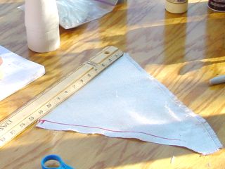 |
Unrolled and measured, this triangle is about 14 inches long by 12 inches at the base. |
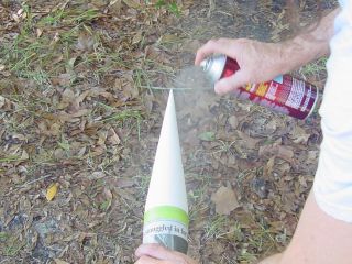 |
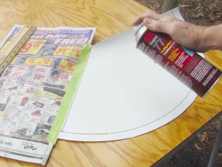
Now you get to see the spray can in action. This is not a trick, not an edited photo, I am really spraying glue here. Why? To stick on the fiberglass cloth. Instead of messing with smelly, sticky fiberglass resin, I'll use the 3M Super 77 to get the cloth to stay in place, then put resin on it. I have not done much fiberglassing before. If you know a good reason why I should not do it this way, please clue me in! So far, it seems to work OK |
 |
Another possible travesty.* I am not using fiberglass resin exactly, but West Systems epoxy. One squirt from each pump is enough to cover this cone. Here I am applying it with a homebuilt brush - a strip of paper towel wrapped around a Popsicle stick and held with a rubber band. The epoxy is worked into the cloth until it is saturated and the epoxy meets the paper base underneath. It is kinda easy to see when this has happened, but it doesn't show up well in the photos. |
 |
Remember I promised to make a different cone? Well I did it, and by golly it sure is pink. Or maybe its "fuschia"
or "mauve" or "chartreuse" or one of those other funny colors that guys can't see.
So I'm not sure any more. But I know it isn't "teal" because that's the color of my truck and
it's green. For added confusion, this is a different base too. In fact, it's a whole different nose cone I made a week ago. This one has a section of PVC tubing glued into the forward end of the base that sticks into the nose cone a little ways. It could be a bacon-saver for the electronics if it ever has a hard landing. I'm showing you this one now and making fun of it because it will be used in some of the photos that follow. Please don't flip out when you see pink. It is not necessarily a flashback. |
 |
This could be fired as is, I am sure. It's been
painted on the inside with two coats of epoxy, giving the paper much
greater strength, so I believe it could handle the stresses of flight in my subsonic airframes. What I'm not sure of is if it could handle the stress of a hard landing. It needs some hardening for that. It's also a bit irregular - the overhang is too wide, there is a loose flap here and there... it needs some finish work. |
 |
Now here is where that little belt sander comes in handy.
I'm sure this could be done by hand, and sure am glad that I
didn't have to do it that way. I kinda like the candy-cane effect. Apparently, this posterboard is only pink on the surface, and white in the middle. This makes it obvious that I have removed most of the surface. For one of these nose cones, I simply coated it with epoxy inside and out a couple of times. It is plenty strong enough to be fired, and would probably hold up well. |
 |
Here is the cone after applying the glass cloth and
epoxy, hardening for a day, and a good rough sanding on the belt
sander. Doesn't look all that different, does it? If I were doing this without power tools, it might be better to cover the rough parts with Bondo and sand that smooth. A "finish coat" of epoxy is applied and allowed to harden. This fills in little gaps and covers surfaces too rough to smooth with the sander. |
 |
Power tools are great, but there is something about hand
finishing that makes a project into art. And its a chance to reshape the decorative fingernails that were "done" on my little belt sander. It does them quick! |
 |
 |
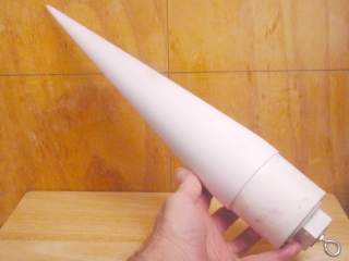
Add a shock cord loop, and it is ready to fly. Add a couple of coats of white primer, and it is rather handsome, if somewhat pointy. |
 |
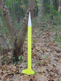 |
The cone looks right at home on the yellow Ariel airframe, giving it a Nike Smoke sorta look.
I
haven't decided what it's final color will be.... Its weight is 351 grams with no electronics. The PML nose cone that came with this kit weighs 185 grams with several coats of paint on it. So my cone is definitely not a winner in the lightweight category. But at least that extra mass is in the right place to increase stability. That might let one use less fin surface.... The PVC parts make up a good portion of the weight, so if they could be dispensed with, or a lighter substitute found.... Or I could just let it go and have a functional nose cone at very low cost. |
 |
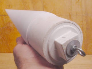
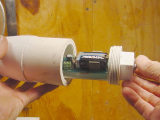
Here is a bonus. That threaded plug seems a good size
for mounting electronics. This plate was intended to
mount my CPR3000 altimeter in the Big Sugar rocket, but I abandoned it in favor of a wooden mount, which worked fine. Guess I should come up with some electronics for this one. Or maybe put in a general purpose mounting bracket so I can decide later. Any ideas? I'm open! |
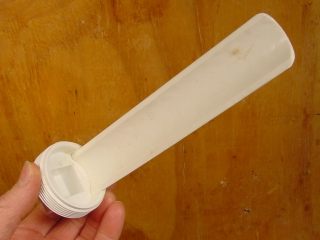 |
Ok, here is a better plan. I found that a 1-1/2 inch
PVC pipe fits inside the end of the 2 inch cap with just a little
wiggle room. So I cut away all but 1/4th of it, sanded the end so
that it fits evenly, and have glued it into the cap with PVC cement. This one is extra long. I glued it first, then trimmed it down to fit the nose cone |
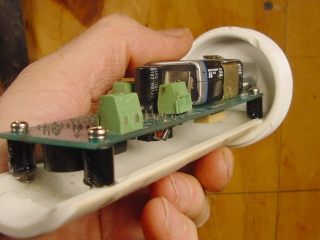 |
Using PC board standoffs from Radio Shack, I drilled holes in
the PVC and embedded the screws in epoxy inside those holes. The
altimeter can be removed by taking out the top screws, but those
standoffs are there to stay. The end of the altimeter is butted against the PVC cap - I don't want to count on those standoffs supporting it under high acceleration. |
 |
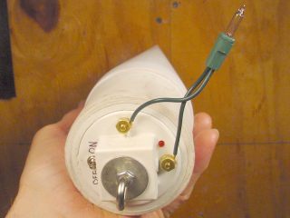
A quick test to make sure it fits... yes! it goes in easily. Now I need to figure out how to run the wires. Also, the altimeter needs a vent. The simplistic solution is just to drill a hole and run all the wires through it to the altimeter switch, and to the ejection charge(s) An alternative would be to put the switch on the base plug, and to use brass screws as terminals leading from the inside of the cone to the outside base. Maybe I'll get some small brass screws on my way home tomorrow... |
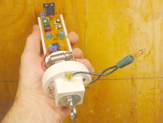 |
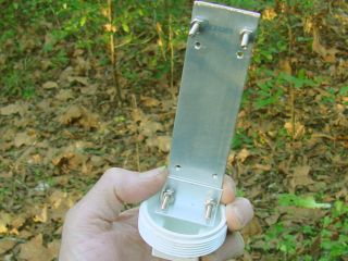
OK. Did it. Another base with mounting plate,
this time attaching the timer Don Lorenzo gave me a year ago.
Finally I get around to doing something with it. From left to right, the base plug has a power switch, a brass screw serving as one terminal for the e-match, a status LED, and the other e-match terminal. On the other side, I just soldered a wire in the slot of each screwhead. They are the flat-slotted type, so this seems to make a pretty good connection. The 9v battery is held under the massive overkill hose clamp... well it's the smallest I have that will fit. It is clamped down with a short section of the PVC base cut off yesterday's project. This squeezes the battery in there pretty well, and the bottom of it is resting on the base plug anyway. |
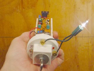 |
A test.....and it works! |
 |
Now I need to put a weight on that microswitch, hook up a real ejection charge, and test it in the airframe.... I'll do that before it flies. |
| Remember the plot from Hans' graph way up at the top of this page? Here is a plot of a 3/4 power nose cone. I can't help but note that it bears a resemblance to the true cone. And it is one of the "better" shapes.  |
Apparently a small change in geometry can make a big difference in aerodynamics. So I'm considering ways to build up the cone cone to make this shape. Tried deforming a cone soaked in water- didn't work. Perhaps more fiberglass could be added, a coating of Bondo or some other reasonably lightweight material. Yeah, I know Bondo won't survive Mach transition, but my airframes will not approach that speed. Ideas and suggestions are welcomed! This graphic generated by the Nose Cone Design spreadsheet for Excel and distributed by Info-Central. Thanks to by Kemal Payza for this excellent utility. But for now, the cone cone will have to do. |
| First Launch 2/11/06 OK, I'm back! And I did get a chance to flight test this nose cone on the Sugar Rush at the February NEFAR launch. Good news is that the flight went well.... to about 70 feet. At that point the motor experienced a "mild" CATO and the aft end suffered rapid disassembly. The fore end continued up to perhaps 200 feet and fell without the benefit of parachute. It landed flat, and the nose cone, altimeter, and forward section survived without serious damage. The CATO was my fault, the nose cone had no part in that act of idiocy, despite its appearance. So one could call it a successful stress test for the nose cone, but not a very complete flight test. I'm rebuilding the airframe, have ordered another motor, and plan to try it again in March. |
| Feedback from rocketry lists, 1/06 Steve Shannon wrote: Hi Jimmy, Very nice article. You make it look easy enough to try. One of your sentences on your web site said "Another possible travesty. I am not using fiberglass resin exactly, but West Systems epoxy." That is definitely not a travesty. You did the right thing there. West Systems is designed to be used to wet out fiberglass cloth and is very strong. Most so called fiberglass resins are usually polyester resins which are not as strong, but are more volatile. Nice site! Steve Shannon Big Sky Rocketry Association NAR 78228, TRA 8716 L3 Kevin Patterson wrote: Nice work Jimmy! We have made paper ones filled with foam up to 10".
They aren't pretty, but are cheap, easy and quick to make, all good for us
Trailer Trashers! :-) The newest ones we have been using G-10 fiberglass
instead of paper, a little more money, but quicker to make, no need for the
glassing step and the foam doesn't deform the G-10, making finishing a snap.
--
|
Steve Shannon wrote:
|
Jimmy Yawn Recrystallized Rocketry jyawn@sfcc.net 1/22/06 rev 2/22/06 |